This is one of my early projects.
Motivation & Goal
The goal of this project was to achieve a non-photorealistic rendering effect using feature line detection and attribute-based color mapping.
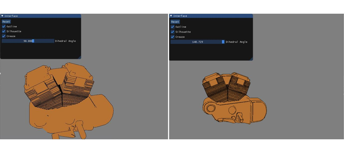
Instead of post-processing edge detection, this project uses an edge buffer to detect silhouettes, and a threshold on the angle between two front-facing polygons to detect crease edges.
Features
Feature Lines (Silhouette & Crease)
Instead of post processing edge detection, the program using edge buffer to detect silhouette, and a threshold of angle between two front-facing polygons to detect crease edges.
//adjacent list
struct Node {
unsigned int v; //vertex id(index)
unsigned int f = 0; //front face bit
unsigned int b = 0; //back face bit
std::vector<glm::vec3> norms; //normals of 2 faces
};
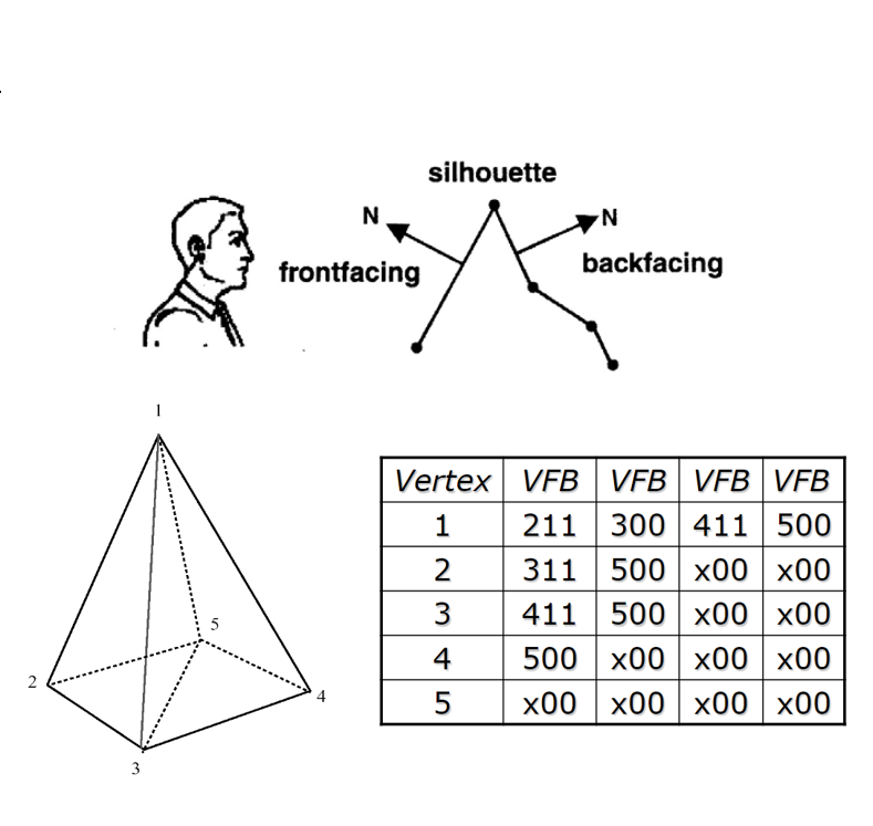
// detect silhouette
for (int j = 0; j < edgeBuffer.size(); ++j) {
Vertex v0, v1;
for (auto it = edgeBuffer[j].begin(); it != edgeBuffer[j].end(); ++it) {
//if front bit and back bit are both 1, which means it is a silhooute
if ((*it).b && (*it).f) {
v0 = ourModel.meshes[0].vertices[j];
v1 = ourModel.meshes[0].vertices[(*it).v];
//cout << j << " " << (*it).v << " " << (*it).b << " " << (*it).f << endl;
vertices.push_back(v0.Position);
vertices.push_back(v1.Position);
}
}
}
// detect crease
for (int j = 0; j < edgeBuffer.size(); ++j) {
Vertex v0, v1;
for (auto it = edgeBuffer[j].begin(); it != edgeBuffer[j].end(); ++it) {
//if it's front face
if (!(*it).f && !(*it).b) {
v0 = ourModel.meshes[0].vertices[j];
v1 = ourModel.meshes[0].vertices[(*it).v];
if (it->norms.size() >= 2) {
glm::vec3 norm1 = it->norms[0];
glm::vec3 norm2 = it->norms[1];
if (glm::dot(norm1, norm2) <= glm::cos(glm::radians(180.f - creaseAngle))) {
vertices.push_back(v0.Position);
vertices.push_back(v1.Position);
}
}
}
}
}
Texture
Based on RGB to HSV conversion, I implemented shader functions to convert between RGB and HSV color spaces for hue-based color manipulation.
vec3 rgbTohsv(vec3 c)vec3 rgbTohsv(vec3 c)
{
    vec4 K = vec4(0.0, -1.0 / 3.0, 2.0 / 3.0, -1.0);
    vec4 p = mix(vec4(c.bg, K.wz), vec4(c.gb, K.xy), step(c.b, c.g));
    vec4 q = mix(vec4(p.xyw, c.r), vec4(c.r, p.yzx), step(p.x, c.r));

    float d = q.x - min(q.w, q.y);
    float e = 1.0e-10;
    return vec3(abs(q.z + (q.w - q.y) / (6.0 * d + e)), d / (q.x + e), q.x);
}

vec3 hsvTorgb(vec3 c)
{
    vec4 K = vec4(1.0, 2.0 / 3.0, 1.0 / 3.0, 3.0);
    vec3 p = abs(fract(c.xxx + K.xyz) * 6.0 - K.www);
    return c.z * mix(K.xxx, clamp(p - K.xxx, 0.0, 1.0), c.y);
}
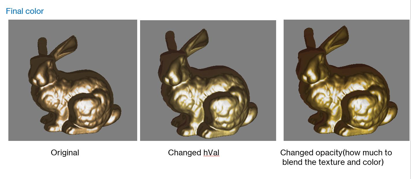
In real-world lighting, surface color appearance changes depending on cool skylight and warm sunlight contributions.
I applied this principle to introduce subtle hue variation across surfaces, simulating real-world lighting shifts.
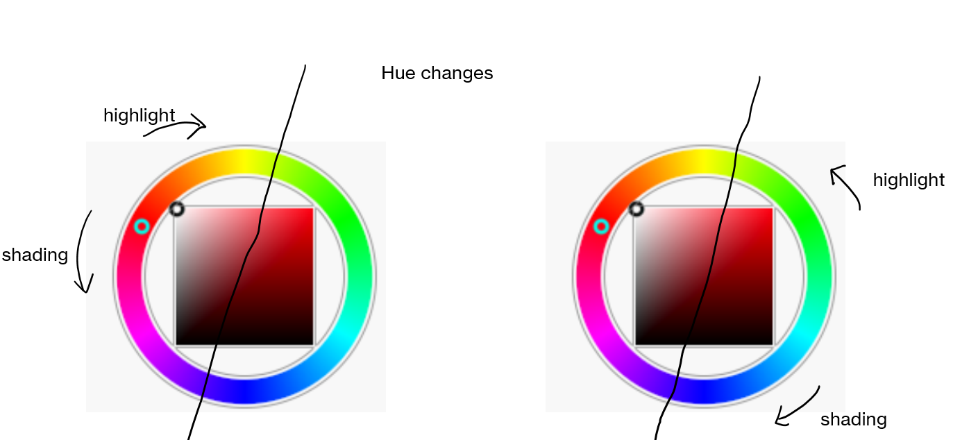
The system applies the user-selected base color onto a grayscale texture, then adjusts the hue to create a natural-looking stylized effect.
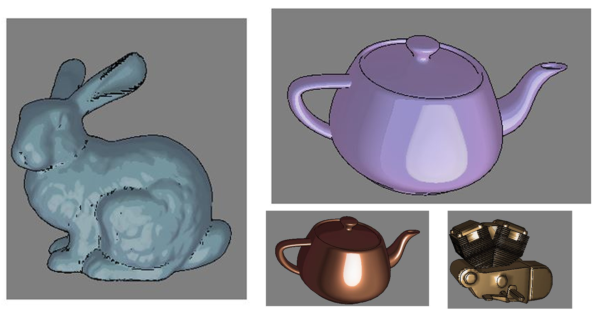
Gallary
In the end, the renderer achieved a pleasing non-photorealistic effect, as shown below: