This shader is implemented in Unreal Engine 5, following the workflow in Cross-Hatching material Post Process [UE5, valid for UE4].
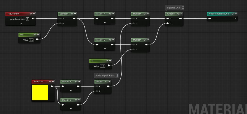
Adjusted Screen UVs
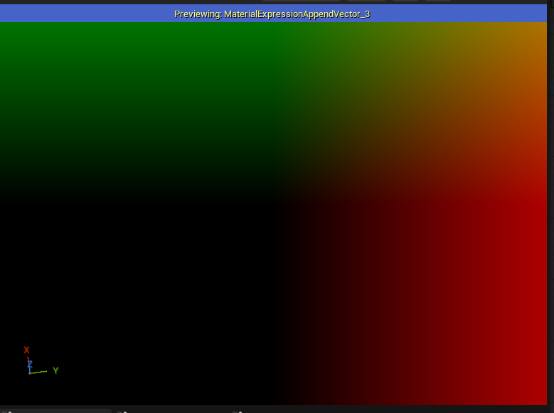
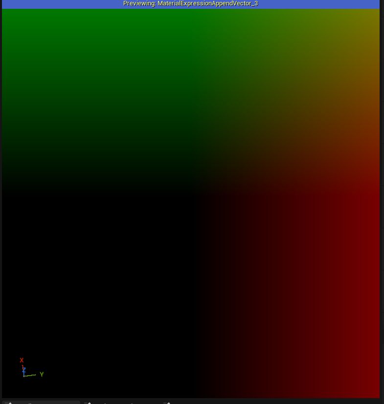
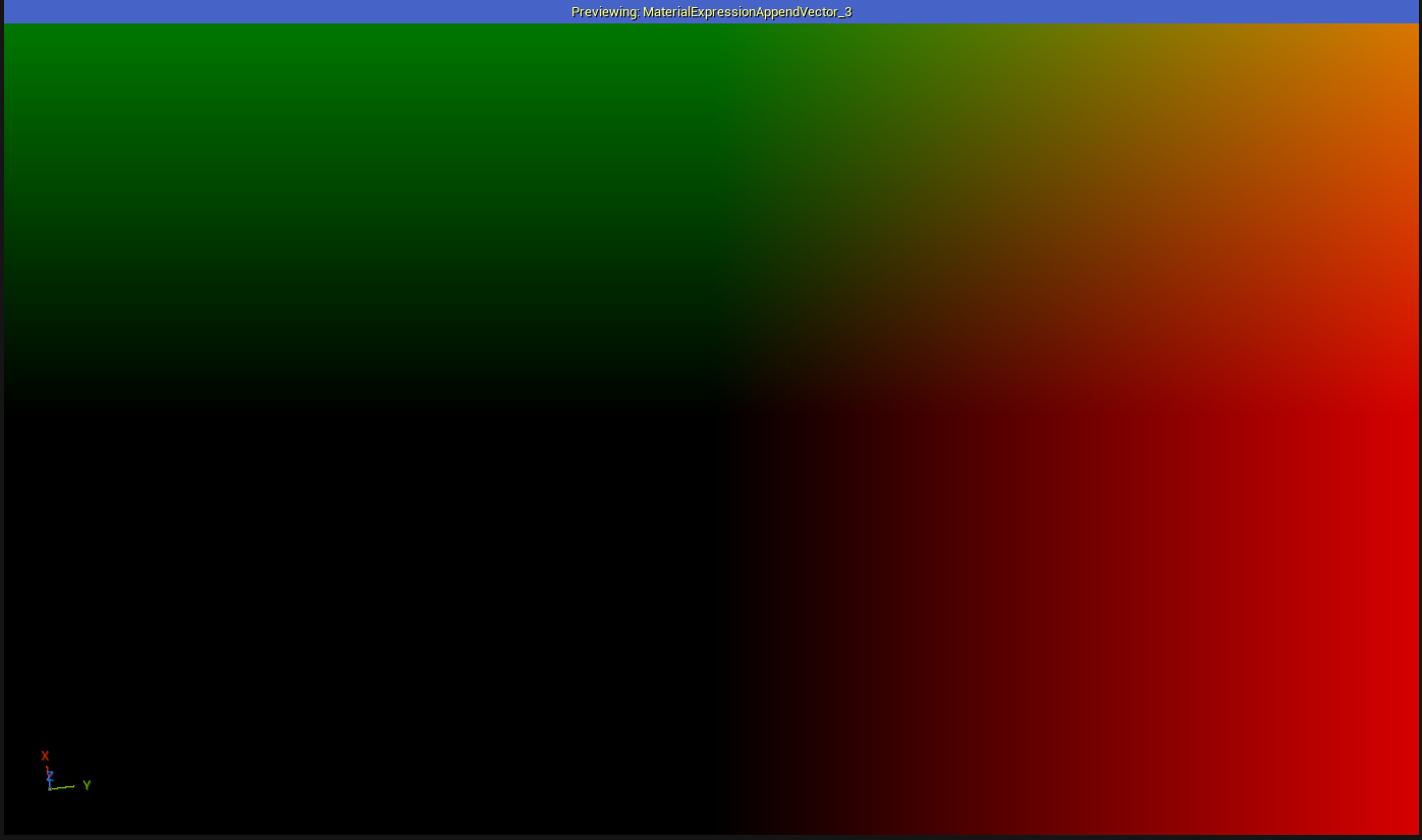
Because the line patterns are generated from UVs, we must compensate for the viewport’s aspect ratio to prevent distortion when the view size changes. I applied a Frac node so we can have better visialization of it. Notice that no matter how we change the width of the view, it has no effect on the value along y axis.
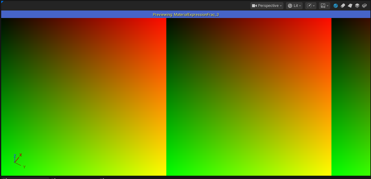
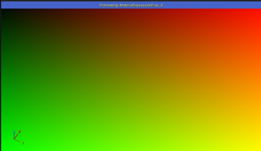
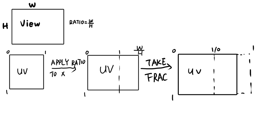
Next step, we need to move the UV origin to the center of the screen, and flip the G channel (Y axis, the height). I’ll explain later why we need to do this.
The final results of our adjusted screen UVs are shown below, as long as the shader nodes.
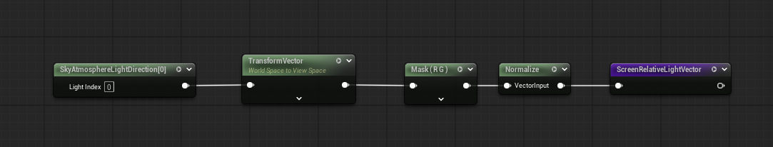
Screen Relative Light Vector
The hatching lines are generated using both the adjusted UVs and the main directional light. Since the UVs are in view space, the light direction must also be transformed into view space for consistent calculations.
This can be done by using TransformVector node. After the transformation, we only use the R and G channels(x and y), since the view space is in 2D dimension. Finally, we normalized the vector for the later computations.
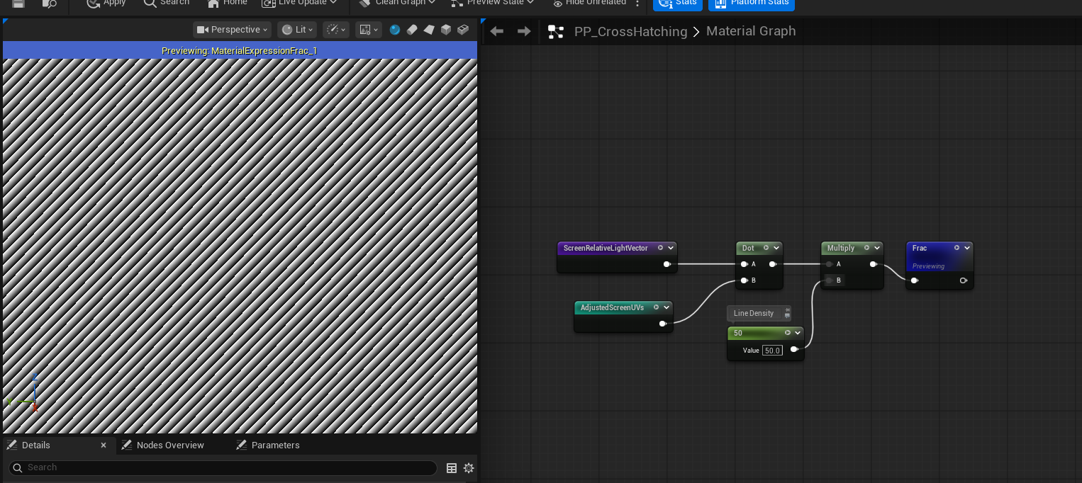
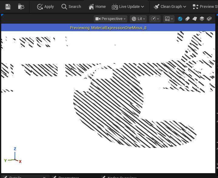
Cross Hatching Lines
Now we can generate our cross hatching line patterns. We start by taking the dot product of our Adjusted Screen UVs and Screen Relative Light Vector. This produces a smooth gradient ranging from black to white, depending on how aligned the UV direction is with the light direction.
Next, we multiply this result by the line density, which controls how frequently the lines reapt. Finally, we apply the Frac node. Since Frac outputs only the fractional portion of the input value(a value between 0 and 1), which is exactly the color range from black to white. Thus, we get a neat, evenly spaced line patterns.
If you are confused about how the dot product works here, try replacing the light vector with a custom float2 node. By manually changing its direction, you can clearly observe how the orientation of the light vector directly influences the direction and appearance of the cross hatching lines.
Right now, our lines are pretty jaggy, that’s because at boundaries of each small gradient segment, the value abruptly jumps between 0 and 1. This causes the visible aliasing in the pattern. To smooth it out, we can remap the value from (0, 1)to (-1, 1), then take its absolute value. Now we will have a nice and smooth line patterns.
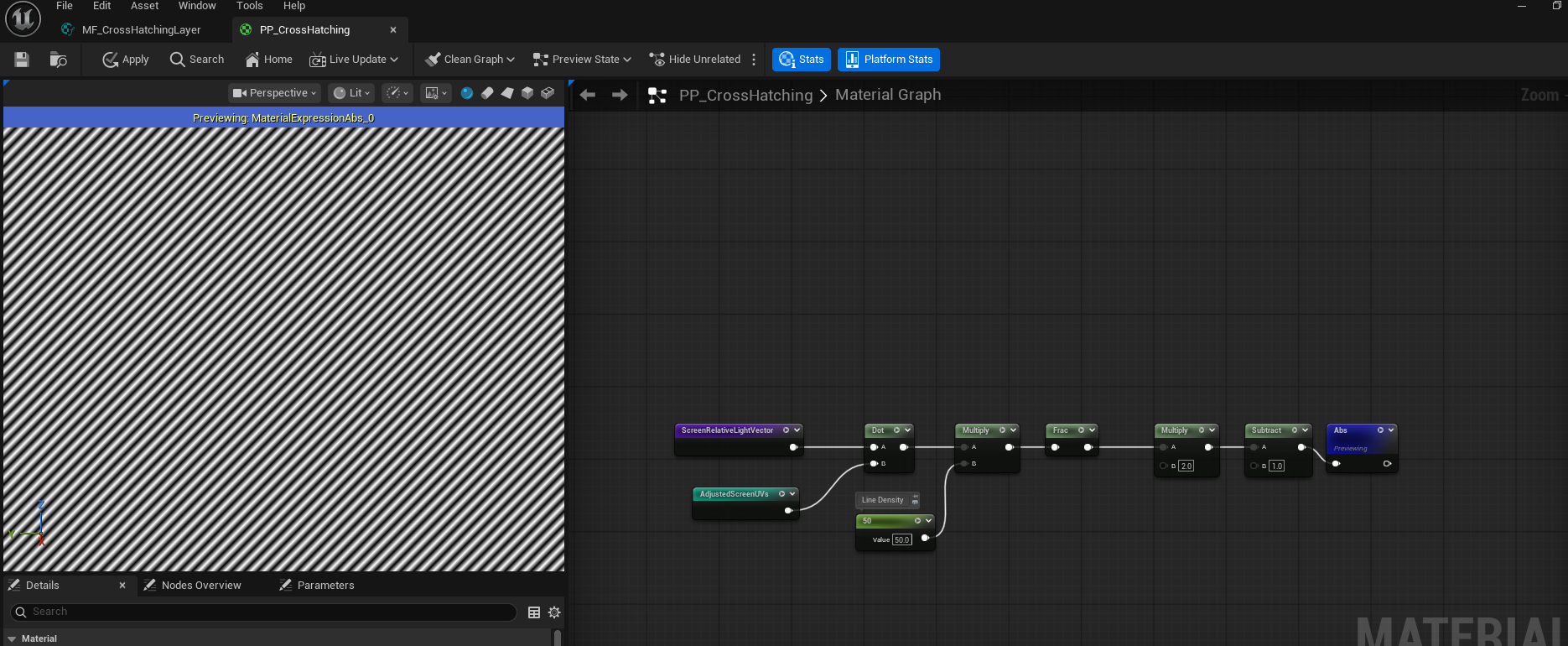
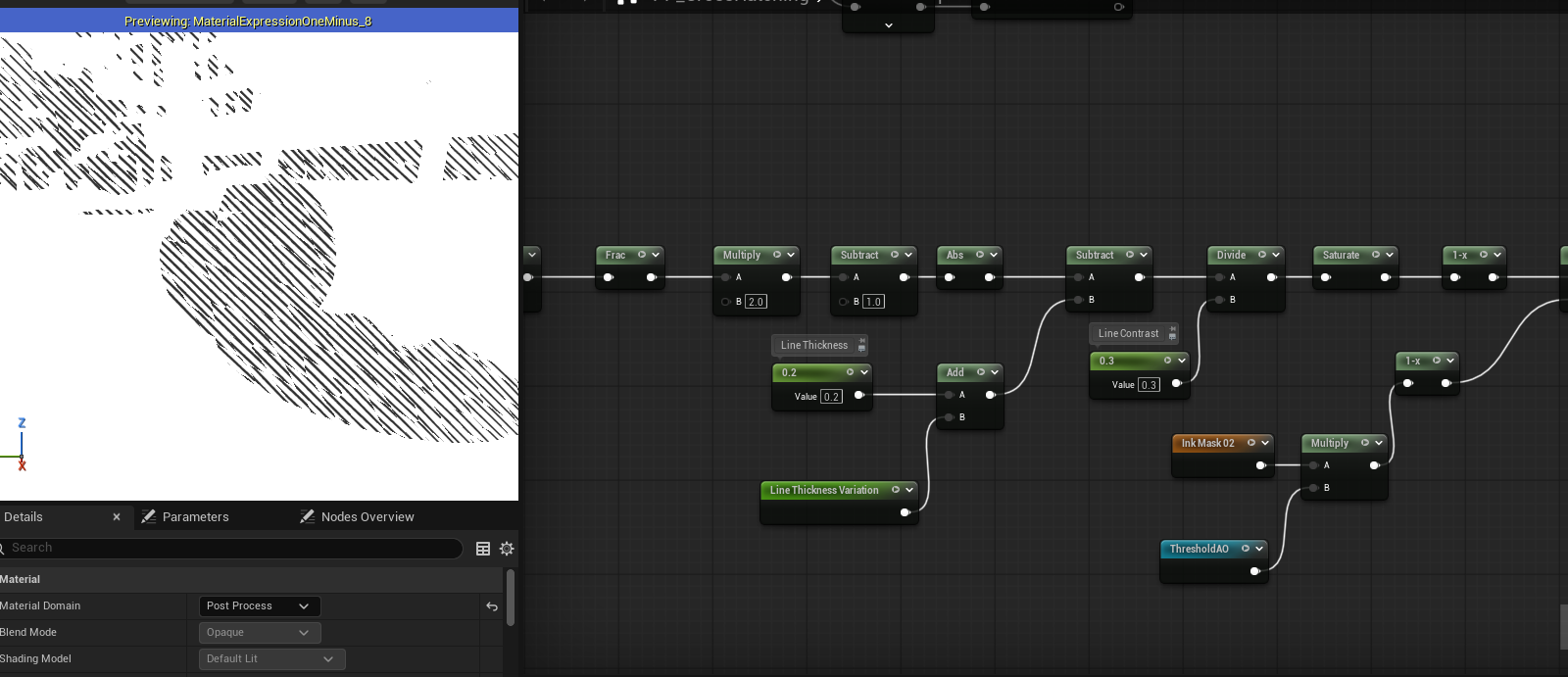
Because our line patterns are composed of many repeating gradient segments from black to white, we can control the line thickness by adjusting how much of each segment remains in the black region. Practically, this means subtracting a line thickness value from the pattern, which shifts more of the gradient below zero and results in thicker lines.
We can further refine appearance by dividing the result by a line contrast value. This scales the gradient and allows us to control how sharp or soft the transition between dark and light areas appears.
Finally, don’t forget to saturate the value after all these operations.
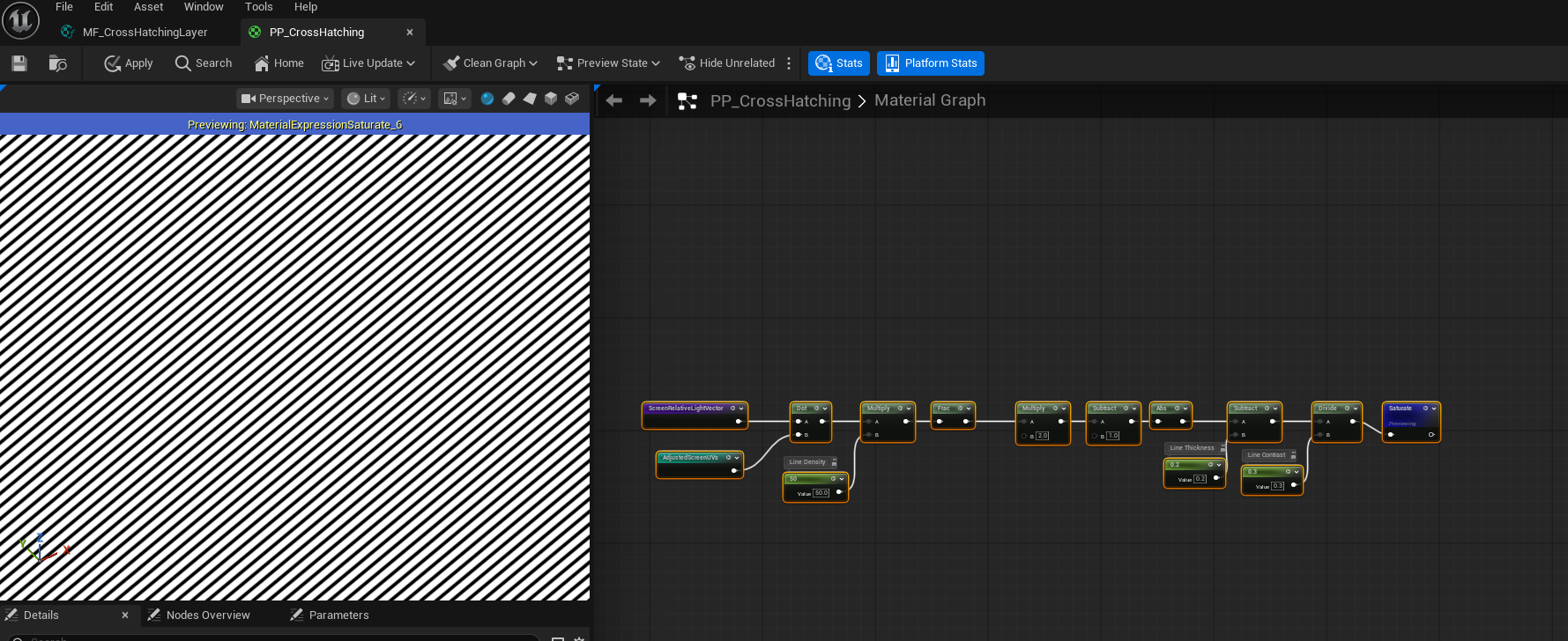
Ink Masks
In traditional drawing, artists use dense lines to represent darker tones and fewer or no lines for lighter areas. We mimic this behavior by generating multiple ink masks based on image luminance and gradient thresholds.
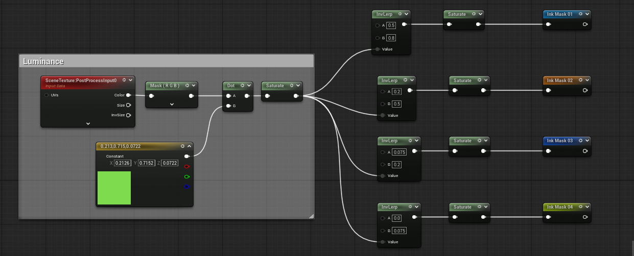
First, we calculate the luminace of the image using Relative Luminance formula:
L = 0.2126 * R + 0.7152 * G + 0.0722 * B.
In the shader, this is implemented by taking the dot product between the RGB value sampled from the post-processing texture and a constant float3(0.2126, 0.7152, 0.0722).
Since artists often layer multiple sets of cross-hatching lines to convey varying degrees of shading, we generate multiple ink masks rather than a single one. Each mask corresponds to a different luminance range and is created using an Inverse Lerp (InvLerp) with distinct threshold intervals. Apply Step node after it to get a black and white mask. By stacking several InvLerp operations with progressively darker ranges, we obtain a set of ink masks that represent increasing shading intensity. These masks are later used to selectively apply different layers of cross-hatching lines, producing a more expressive and hand-drawn appearance.
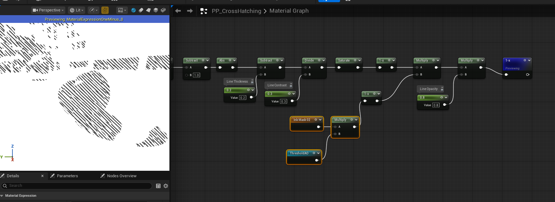
Apply Effect & Line Control
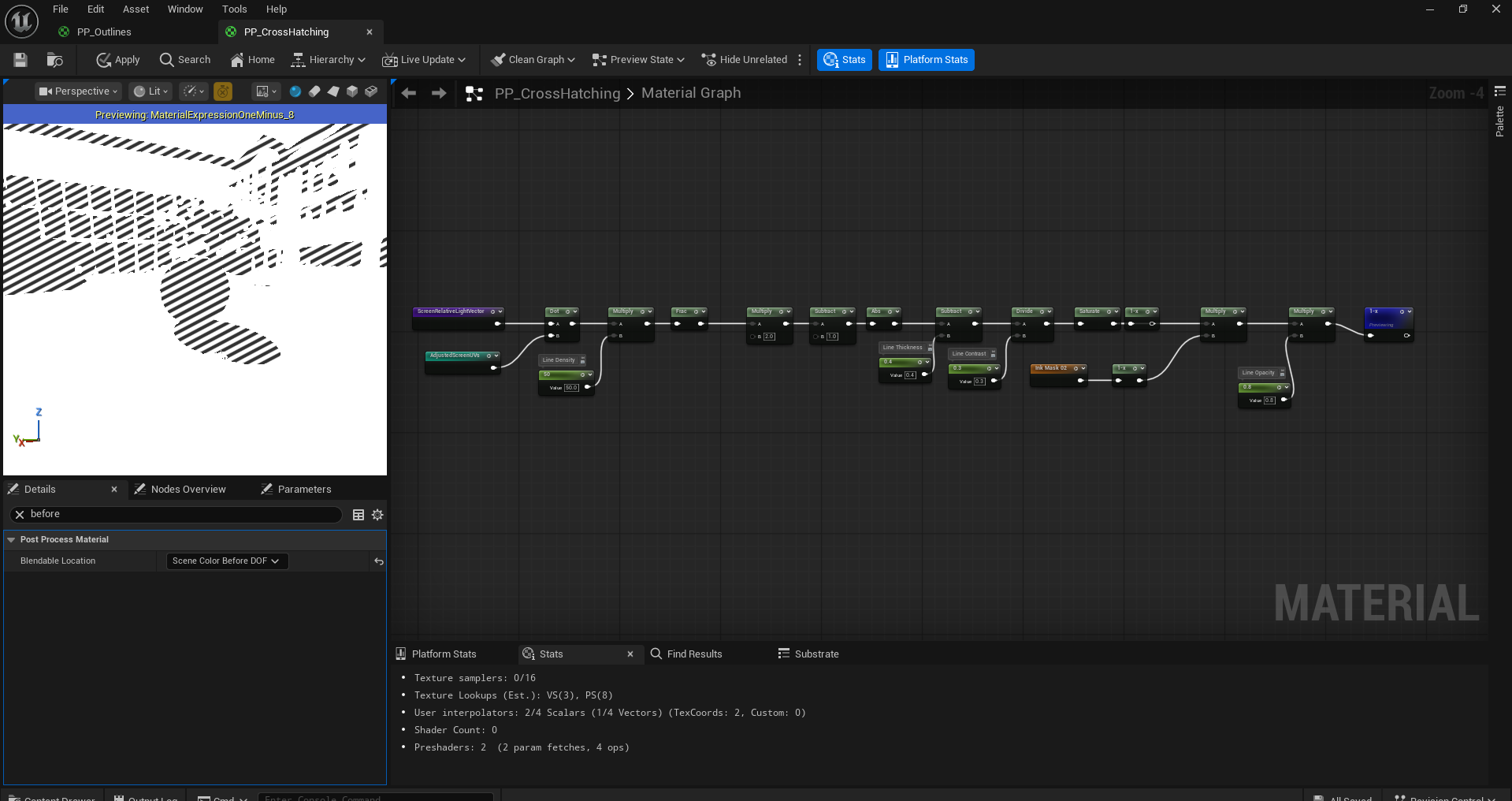
At this stage, the ink mask defines the regions where cross hatching lines should appear, with shaded areas represented as black(0). Since our line paterns are applied where the value is white(1), by multiply operation, we first need to invert the ink msk using OneMinus(1-x) operation. This converts the shaded regions into valid mask areass for applying the effect.
Next, we multiply the inverted ink mask with the generated line pattern, producing corss hatching only in the designated shaded regions. However, this operation results in all non-masked areas becoming black. To restore the background, we can apply another OneMinus(1-x) node to the result. Unfortunately, directly inverting at this stage also unintentionally reverses visiaul properties of the line patterns, such as line thickness and contrast. To resolve this, we can just simply apply OneMinus(1-x) node to the line pattern itself before multiplying it with the ink mask.
Before performing the final inversion, we also introduce a line opacity parameter. By multiplying the masked line pattern with this scalar value, we gain fine control over the visibility and strength of the cross hatching effect.
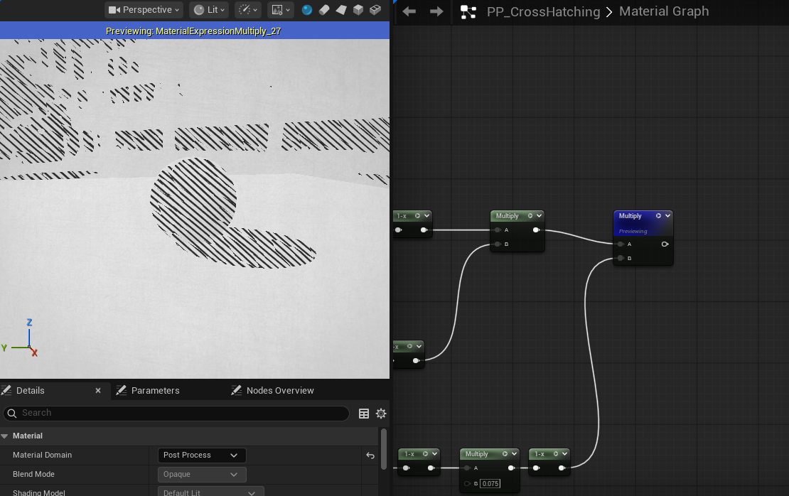
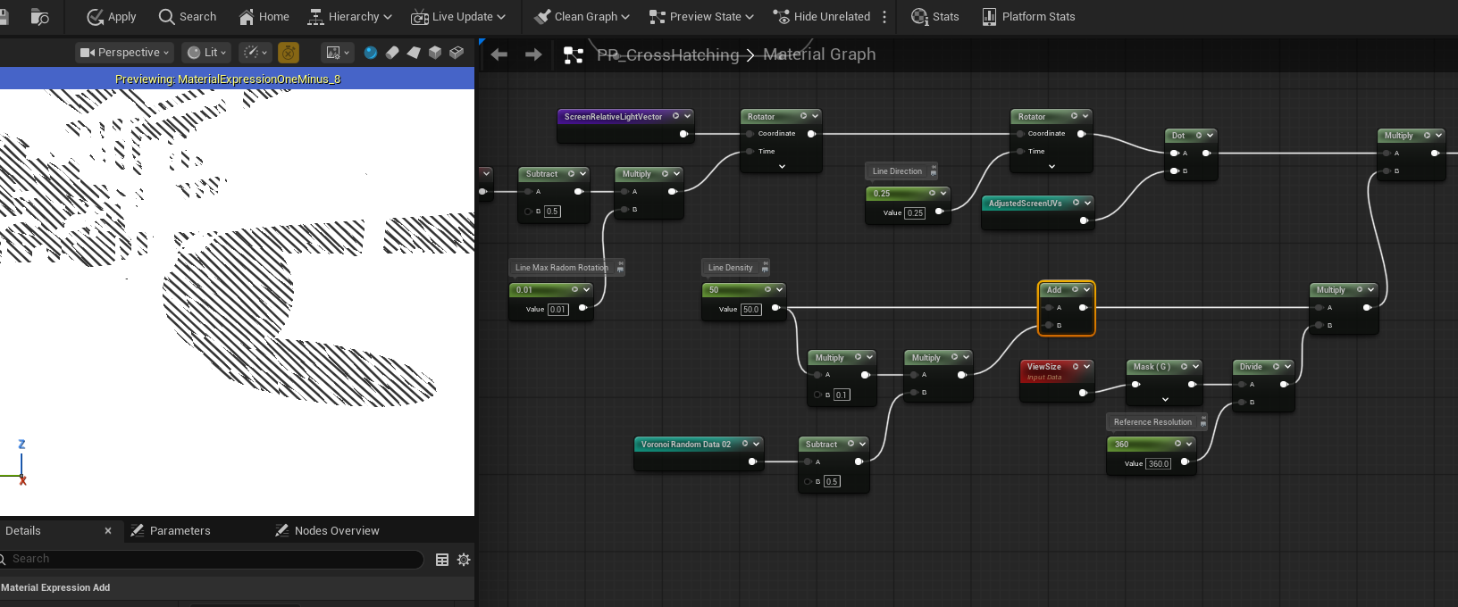
Multi Cross Hatching Line Layers
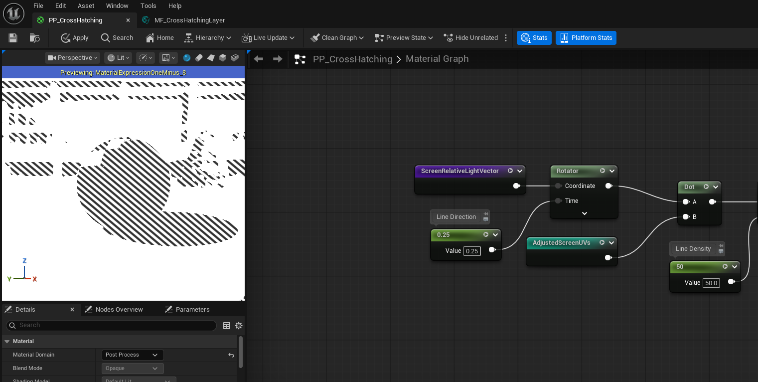
To achieve richer and more expressive shading, we introduce multiple layers of cross-hatching lines, each oriented in a different direction. This mimics traditional drawing techniques, where artists layer strokes at varying angles to represent darker tones and convey form.
We generate these different line orientations by applying a Rotator node to the ScreenRelativeLightVector. By rotating this vector by different angles, we effectively change the direction along which the line pattern is evaluated. Each rotation produces a distinct cross-hatching layer with its own stroke direction.
By stacking several of these rotated line layers—each with a unique rotation angle—we create a multi-directional hatching effect. When combined with the previously computed ink masks, darker regions naturally accumulate more line layers, resulting in denser shading, while lighter regions remain relatively sparse.
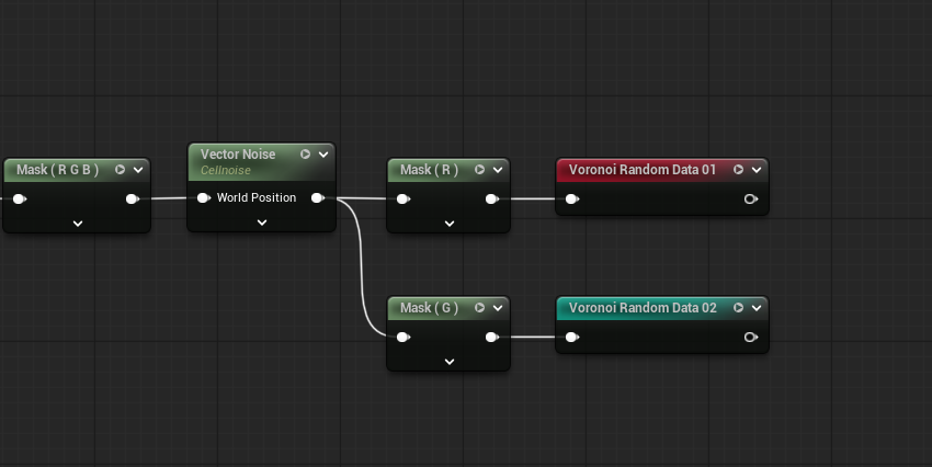
Voronoi
Right now our line patterns are too aligned, that’s not usually hand-drawing cross-hatching lines are in real life, so we need to add some noise to it, and we are gonna use Voronoi to implement it. First, let’s get our AdjustedScreenUVs again and multiply it by the Voronoi Density. The Voronoi in Unreal Engine 5 is 3D, but we only need the noise in 2D space, so we need to append a third coordinate to the UVs as a Voronoi Radmon Seed.
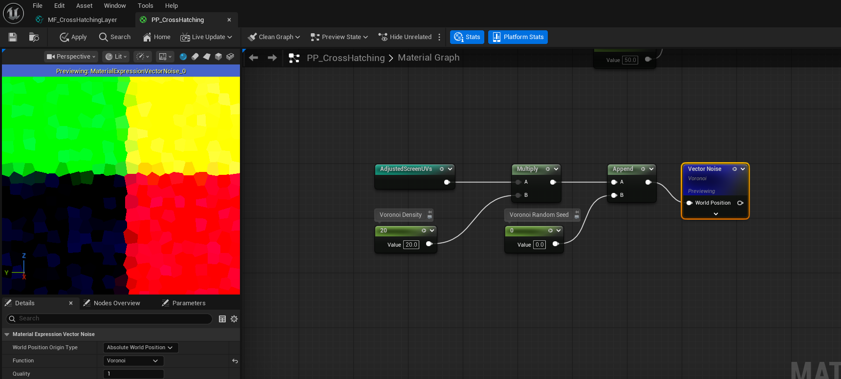
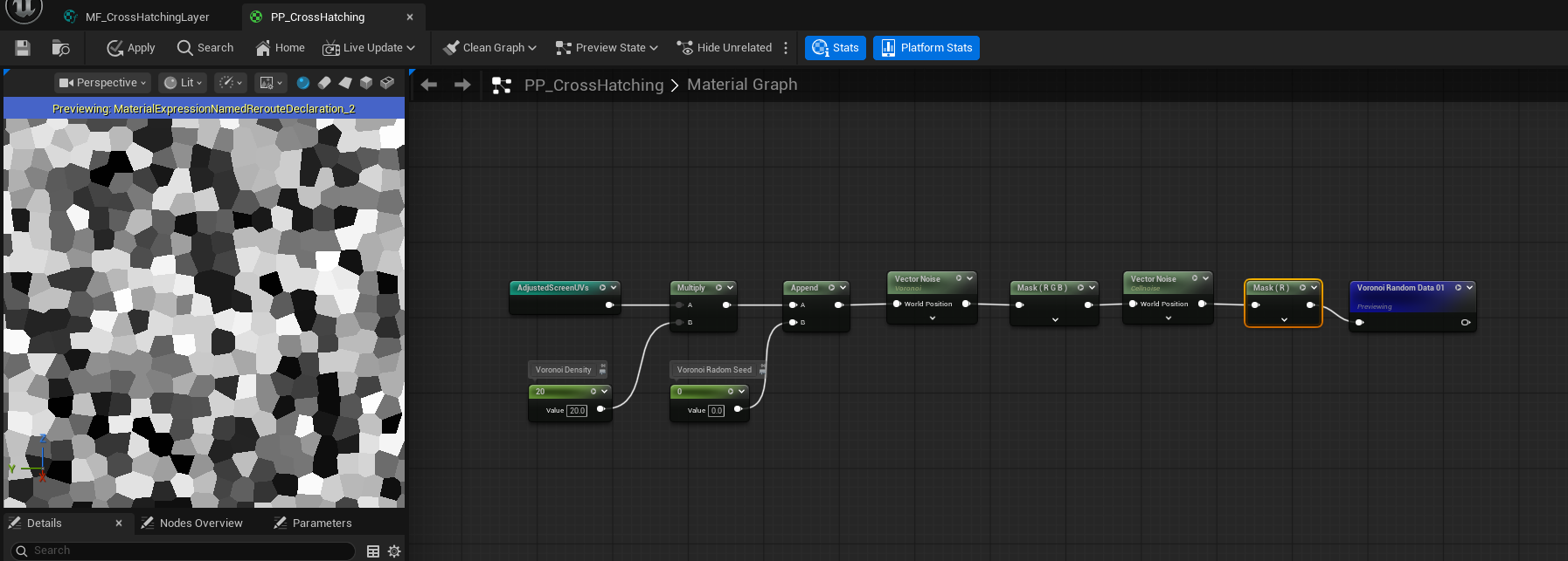
We can also apply Cellnise to the result, to give each cell a different color. So that we can use one channel of this random color as a radom rotation on the light vector to slightly change the light direction in each Vornoi patch. We take one of its channels and name it as Voronoi Random Data
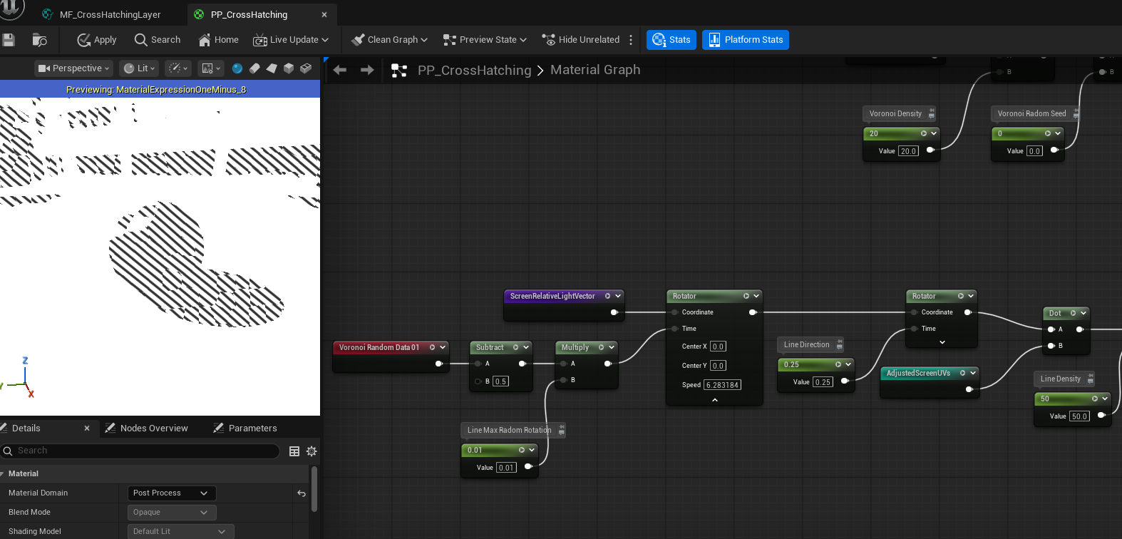
Random Light Rotation
We now use the Voronoi Random Data to introduce per-segment directional variation into the cross-hatching lines. This randomness is applied as a rotation to the line pattern direction, helping to further break up uniformity and reinforce a hand-drawn appearance.
First, we subtract 0.5 from the Voronoi Random value. Since the original data lies in the ([0,1]) range, this remaps it to [−0.5,0.5], allowing the rotation to occur in both clockwise and counterclockwise directions.
Next, we scale this value by a Line Max Random Rotation parameter. This parameter defines the maximum angular deviation applied to each Voronoi cell and provides artistic control over how chaotic or subtle the variation appears.
The resulting value is then fed into a Rotator node, which rotates the ScreenRelativeLightVector accordingly. Because the Voronoi Random value is constant within each cell, all line segments inside a cell share the same rotation, producing coherent yet varied stroke directions across the image.
With this step applied, the cross-hatching lines gain localized directional variation, making the final result feel significantly more organic and closer to traditional ink drawing.
Improve Voronoi
At this stage, the Voronoi cells still appear too square and uniform. In real hand-drawn cross-hatching, stroke groupings tend to be elongated along the stroke direction, not isotropic. To better approximate this behavior, we stretch the Voronoi pattern along the line direction.
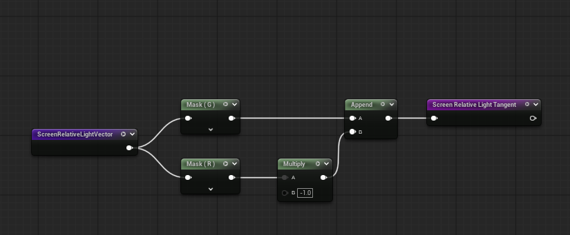
Construct the Light Tangent
We begin by computing a vector perpendicular to the light direction. Starting from the Screen Relative Light Vector, we negate its R channel and swap it with the G channel, producing a perpendicular vector we refer to as the Screen Relative Light Tangent.
This tangent represnets the direction orthogonal to the cross hatching lines.
Directional UV Decomposition
Recall that:
-
The dot product between the light vector and screen UVs produces a gradient whose black–white transition is perpendicular to the line direction.
-
Conversely, the dot product between the light tangent and the UVs produces a gradient whose transition aligns with the line direction.
We use this property to decompose the UVs into two directional components:
-
One along the light direction
-
One along the tangent direction
Anisotropic Voronoi Stretching
To elongate the Voronoi cells along the stroke direction:
-
We multiply the dot product of light tangent · UV by a Voronoi Skew scalar, stretching the pattern along to the strokes.
-
To preserve the overall cell size, we divide the dot product of light vector · UV by the same skew value.
-
We then reconstruct the final UVs by multiplying each scalar component back with its respective direction vector (light vector and light tangent) and summing the results.
These reconstructed UVs are used as the input to the Voronoi noise function.
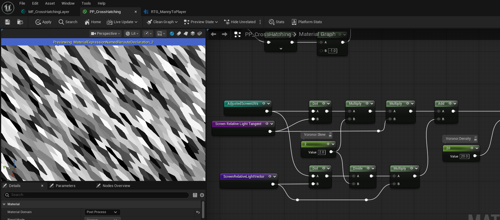
And the cross hatching line patterns look more line hand drawing now as well.
With directional stretching applied, the Voronoi cells become elongated along the cross-hatching direction. This produces more natural stroke groupings and significantly improves the hand-drawn quality of the final cross-hatching lines.
Improve Cross Hatching Lines
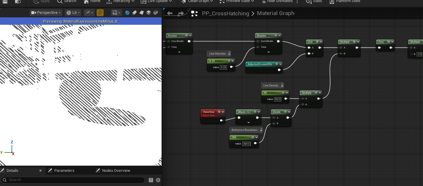
Resolution Reference
To ensure consistent cross-hatching density across different screen resolutions, we introduce a resolution-aware scaling for the line pattern.
We begin by retrieving the current viewport size and dividing it by a Reference Resolution scalar. This produces a normalized scale factor that represents how the current resolution compares to the reference.
We then multiply this scale factor with the Line Density parameter. As a result, the number of cross-hatching lines automatically adjusts based on screen resolution: higher resolutions generate proportionally more lines, while lower resolutions produce fewer, preserving a consistent visual density.
This approach ensures that the cross-hatching effect remains stable and visually coherent across different display sizes without requiring manual tuning per resolution.
Random Line Density
To further reduce uniformity in the cross hatching pattern, we introduce random variation in line density using an additional channel from the Voronoi noise, referred to as Voronoi Random Data 2.
The Voronoi Random Data 2 value lies in the [0, 1] range. We first subtract 0.5 to remap it to [-0.5, 0.5], allowing both positive and negative variation.
Next, we scale the base Line Density by a small factor (e.g. 0.1) to define the maximum amount of variation. Multiplying this value with the remapped Voronoi data produces a density offset in the range:
[-0.05 * LineDensity, 0.05 * LineDensity]
We then add this offset back to the original Line Density, resulting in a final density range of:
[0.95 * LineDensity, 1.05 * LineDensity]
This introduces a subtle ±5% variation in line density per Voronoi cell. The randomness is spatially coherent and stable, preventing flickering while breaking up mechanical repetition. As a result, the cross-hatching appears more organic and closer to real hand-drawn ink work.
Ambient Occlusion
We can also incorporate ambient occlusion to add more depth and grounding to the final cross-hatching result.
First, we sample SceneTexture: Ambient Occlusion and extract a single channel from it. We then apply an InvLerp node to isolate only a specific range of AO values, so that the effect responds only to medium-to-strong occlusion.
Next, we use a Step node to remap the filtered result into a strict black–white mask. This produces a binary occlusion mask that we refer to as Threshold AO.
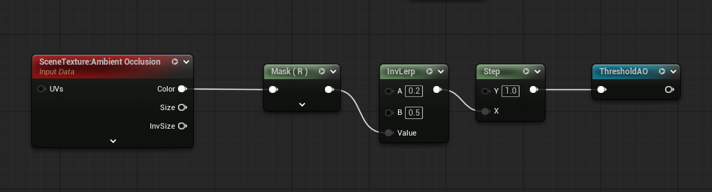
Finally, we multiply Threshold AO with our existing Ink Mask. This reinforces cross-hatching in occluded regions while leaving unoccluded areas unaffected.
By modulating the ink mask with ambient occlusion, darker creases and contact areas naturally receive denser hatching, further enhancing depth and visual realism.
Paper Texture
Line Thickness
To introduce subtle variation in line thickness across the screen, we incorporate a paper texture. A single channel of the paper texture is sampled and remapped from [0,1] to [−0.25,0.25], producing a small signed offset.
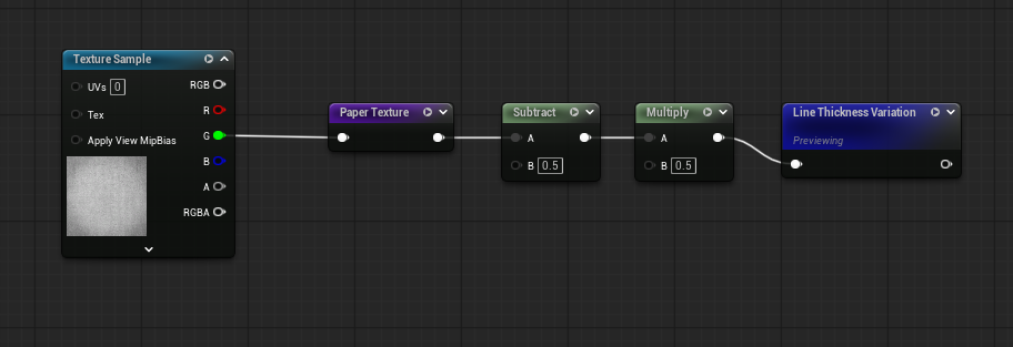
This offset is then added to the base Line Thickness value, injecting controlled randomness that breaks uniformity and enhances the hand-drawn appearance.
Paper Texture Background
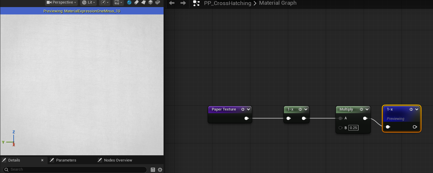
The paper texture can also be used as a background to further enhance realism. Ideally, the final result should be multiplied by the paper texture; however, the original texture is relatively dark, which would overly dim the output. To address this, we remap the texture values to a brighter range.
This remapping is achieved by applying a OneMinus operation, scaling the result by a small factor, and then applying OneMinus again. Let v denote the original texture value: 0 < v < 1 0 < 1 - v < 1 0 < 0.25 * (1 - v) < 0.25 0.75 < 1 - 0.25 * (1 - v) < 1 0.75 < v’ < 1
After remapping, the new value v′ lies in the range [0.75,1], preserving the texture detail while significantly reducing its darkening effect.
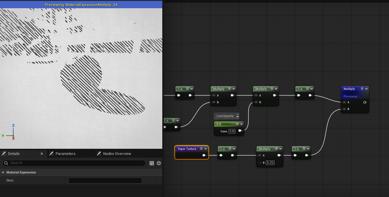
Finally, this remapped paper texture is multiplied with the rendered result, adding a subtle paper grain to the background without overpowering the line work.
Shadow Depth
We begin by separating shadowed regions using the Dot product between the *World Normal and the main light direction. This produces a scalar value representing how much each surface faces the light. The paper texture is then added directly to this value to introduce subtle variation.
Since the effect should only apply to shadowed areas, we isolate the shadow range by applying an InvLerp, followed by a Saturate to clamp the result to [0,1]. The value is then multiplied by itself to amplify contrast, emphasizing darker regions.
Next, we apply the same remapping process used for the Paper Texture Background, shifting the result into a lighter range to prevent the shadows from becoming overly dark. This remapping step can be applied a second time to further soften the shading and introduce a degree of transparency.
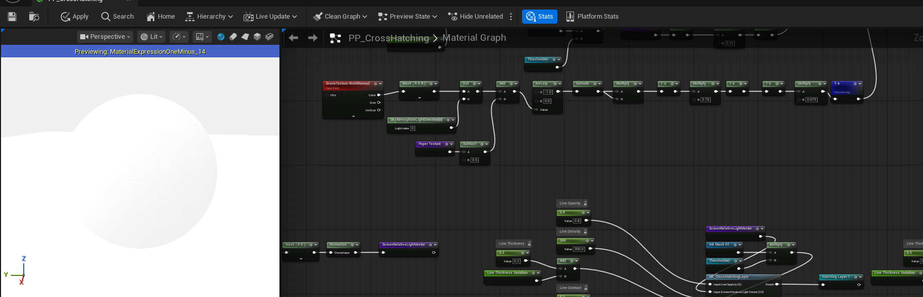
Finally, the processed shadow depth mask is multiplied with the cross-hatching result, producing a balanced and visually coherent shading effect.